UML Diagrams
Overview
Unipress uses PlantUML to generate comprehensive UML diagrams that visualize the system architecture, data flow, and component relationships. These diagrams are maintained as text files and automatically generated as PNG images.
Available Diagrams
1. Architecture Overview
File: docs/uml/architecture-overview.puml
Image: docs/uml/ArchitectureOverview.png
Shows the high-level system architecture including:
Core framework components
Game implementations
Infrastructure components
External dependencies
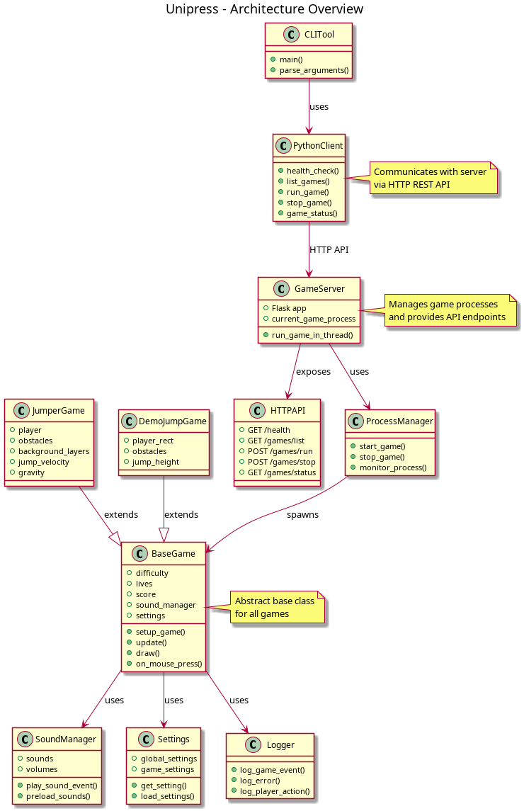 *System architecture showing core components and relationships - [Click to enlarge](../_static/ArchitectureOverview.png)*
2. Class Hierarchy
File: docs/uml/class-hierarchy.puml
Image: docs/uml/ClassHierarchy.png
Displays the inheritance structure:
BaseGame abstract class
Concrete game implementations
Core system classes
Interface relationships
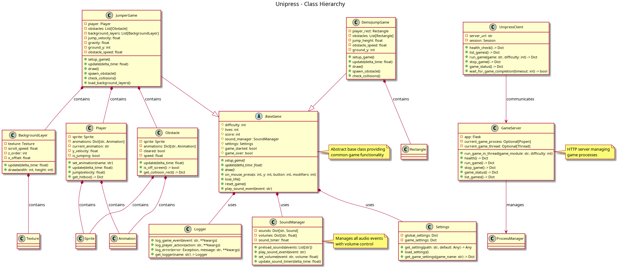 *Class inheritance and interface relationships - [Click to enlarge](../_static/ClassHierarchy.png)*
3. Data Flow
File: docs/uml/data-flow.puml
Image: docs/uml/DataFlow.png
Illustrates how data moves through the system:
User input processing
Game state management
Asset loading and caching
Score persistence
Logging and monitoring
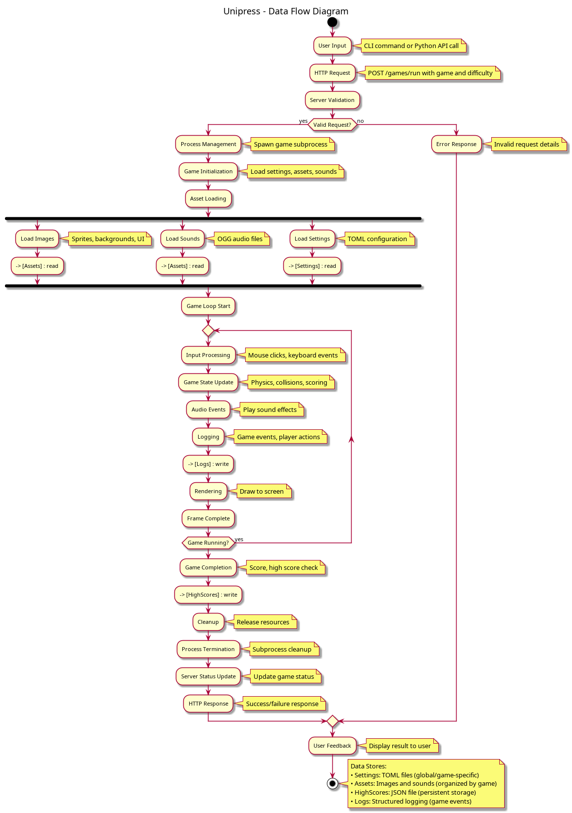 *Data flow through the system components - [Click to enlarge](../_static/DataFlow.png)*
4. Deployment Diagram
File: docs/uml/deployment-diagram.puml
Image: docs/uml/DeploymentDiagram.png
Shows the deployment architecture:
Container structure
Network communication
External services
Resource allocation
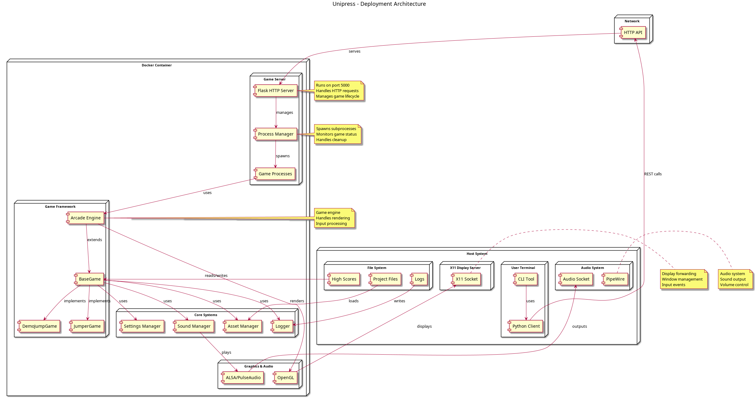 *Deployment architecture and container structure - [Click to enlarge](../_static/DeploymentDiagram.png)*
5. Game Lifecycle
File: docs/uml/game-lifecycle.puml
Image: docs/uml/GameLifecycle.png
Describes the game execution flow:
Initialization sequence
Main game loop
State transitions
Cleanup procedures
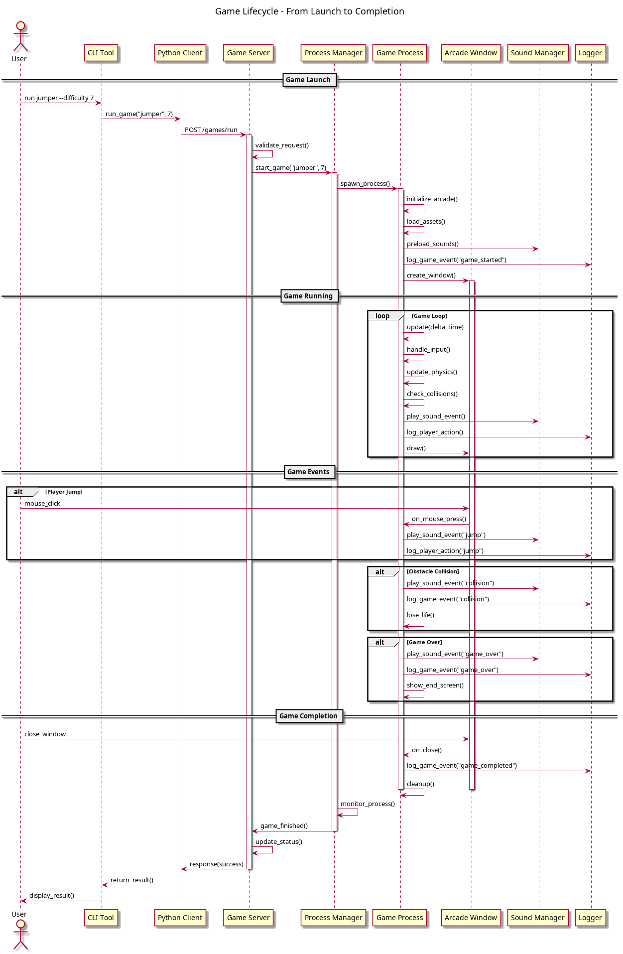 *Game execution lifecycle and state transitions - [Click to enlarge](../_static/GameLifecycle.png)*
Diagram Conventions
Naming Standards
Files: Lowercase with hyphens (e.g.,
architecture-overview.puml)Images: PascalCase (e.g.,
ArchitectureOverview.png)Components: Clear, descriptive names
Visual Standards
Colors: Consistent color scheme across diagrams
Shapes: Standard UML notation
Layout: Logical flow from top to bottom, left to right
Annotations: Clear labels and descriptions
Content Guidelines
Scope: Each diagram focuses on a specific aspect
Detail Level: Appropriate abstraction for the target audience
Consistency: Related diagrams use consistent terminology
Maintenance: Diagrams updated with code changes
Generating Diagrams
Prerequisites
# Install PlantUML
sudo apt-get install plantuml
# or
brew install plantuml
Build Commands
# Generate all diagrams
cd docs/uml
plantuml *.puml

# Generate specific diagram
plantuml architecture-overview.puml

# Generate with custom theme
plantuml -theme path/to/theme.puml *.puml
Makefile Targets
# Build all diagrams
make uml

# Clean generated images
make clean-uml

# Watch for changes
make watch-uml
Diagram Maintenance
Update Process
Modify PlantUML source (
.pumlfiles)Regenerate images using PlantUML
Review changes for accuracy
Commit both source and images
Version Control
Source files: Always commit
.pumlfilesGenerated images: Commit PNG files for easy viewing
Changes: Update diagrams when architecture changes
Quality Checks
Syntax validation: PlantUML validates syntax
Visual review: Check generated images
Consistency: Ensure diagrams align with code
Documentation: Update related documentation
Using Diagrams
In Documentation

*System architecture showing core components and relationships*
In Presentations
PNG format: High quality for presentations
SVG format: Scalable for different screen sizes
PDF export: For printed materials
In Development
Reference: Use diagrams for architectural decisions
Onboarding: Help new developers understand the system
Planning: Guide feature development and refactoring
Advanced Features
Custom Themes
Create custom PlantUML themes for consistent styling:
!theme custom-theme
@startuml
' Diagram content
@enduml
Include Files
Reuse common elements across diagrams:
!include common-elements.puml
@startuml
' Diagram content
@enduml
Dynamic Content
Generate diagrams with external data:
# Generate diagram with current data
python generate-diagram.py > dynamic-diagram.puml
plantuml dynamic-diagram.puml
Best Practices
Design Principles
Simplicity: Focus on essential relationships
Clarity: Use clear, descriptive names
Consistency: Maintain visual and naming standards
Completeness: Include all relevant components
Maintenance
Regular updates: Keep diagrams current with code
Automated generation: Use CI/CD for diagram updates
Review process: Validate diagrams with team
Documentation: Explain diagram purpose and scope
Collaboration
Shared understanding: Ensure team consensus on diagrams
Feedback loops: Incorporate developer feedback
Evolution: Adapt diagrams as system grows
Training: Help team understand diagram conventions